Four Point Projection
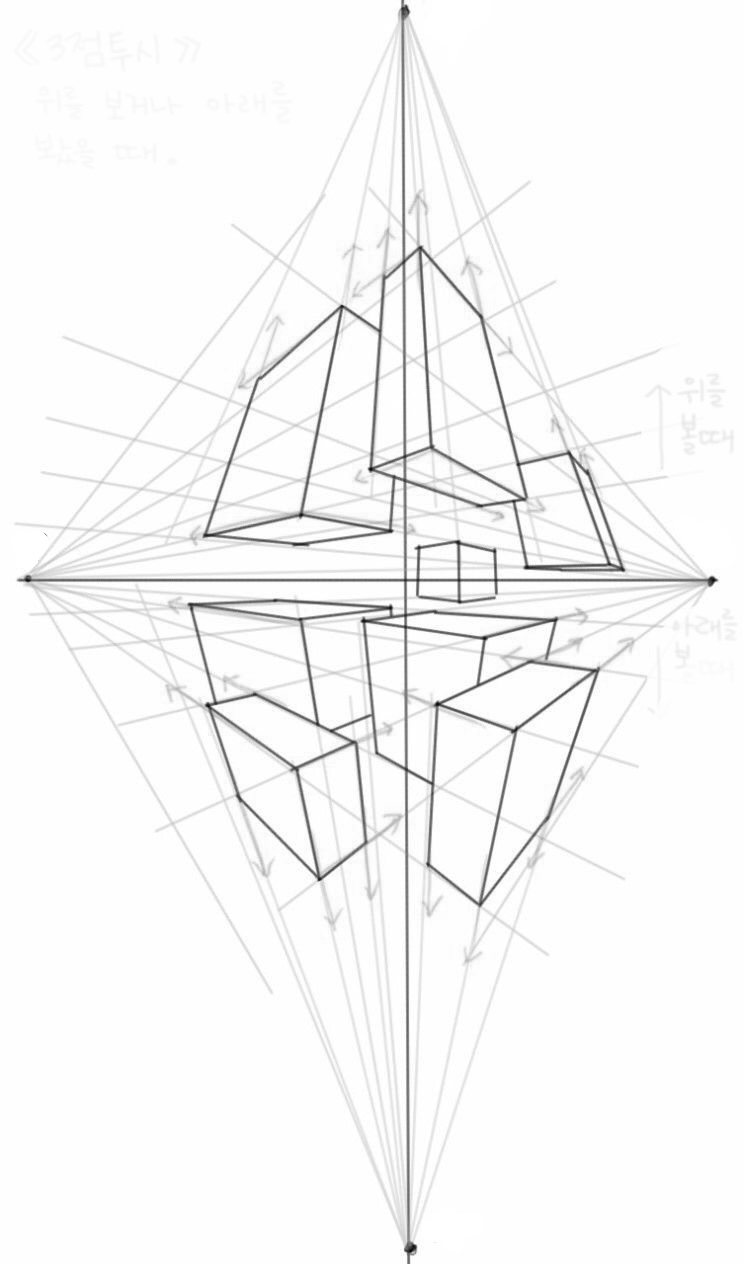
The error that many drafters make is to try to create a Four Point Projection out of two 3 Point grids. As we discovered earlier, there is a problem with objects that straddle the horizon. The usual fix is to render those objects in Two Point Perspective, as with the cube at the centre of this rendering. So rather than a unified projection, it is three separate co-existing grids. It works until a central object gets too tall, or objects have to overlap. Then the system falls apart.
This construct has limited value, except to help explain how the camera uses Three Point Projection. The examples we have been discussing have usually been a fairly large field of view rendered onto a flat, vertical Picture Plane. Most often, the camera lens will capture only a portion of the available field of view. As the camera moves, it changes the angle of the Picture Plane, and thus changes the Perspective. Making sense of this Four Point rendering is a bit like stitching together several photos to create a panorama.
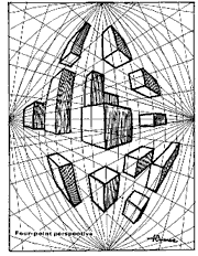
This drawing by Dick Termes illustrates a Four Point Perspective system which maintains a straightline perspective for the horizontal vanishing points and a curvilinear perspective for the vertical vanishing points. All vertical orthogonals are curved. Objects can be placed above and below the horizon and appear to be viewed from the same Observation Point. This construct manages to resolve the rendering into a single unified projection, but the implication is that there is no Central Vanishing Point. That creates a problem for me since the observer clearly has a point of view.

